My GPS module became unresponsive after about ten months of ownership and then again in the spring of 2017. Why is unclear, but this was certainly discouraging. The scope was under warranty when this happened but the thought of crating up the scope for return to the factory was unappealing.
The GPS capability is a nice feature but is hardly mandatory. I could workaround the problem just by entering the date and time into the hand controller when setting things up. But it bothered me that the unit had apparently failed, and not being one to leave well enough alone, I naturally felt the need to delve into the telescope!
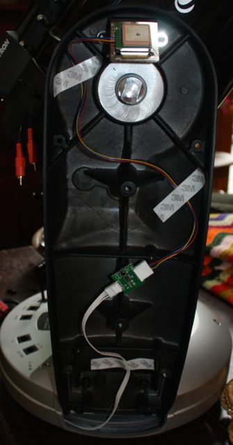
What I found was a small GPS module and interface board within one fork arm – the one with the handle. And searching on-line for mention of similar issues yielded some results; users had reported their GPS units stopped functioning after a time or took a long time to lock up. In my case the GPS failed to work at all, no matter how much time it sat under clear skies.
Reports suggested that these modules contain a rechargeable lithium cell which aids in the GPS quickly locking up on subsequent uses. These eventually fail or wear out.
(Note: I recently participated in a thread over at TeamCelestron.com, where the following comment was posted by a Celestron Engineer: “Actually there have been at least 3 different versions of the GPS module. Once we have something that works we don’t change unless we are forced to change, usually because whoever was making them stopped making them. The current modules went end of life 3 months ago, and we bought enough to last until we can get some new modules in their place. It is one of the things I am working on this week.“)
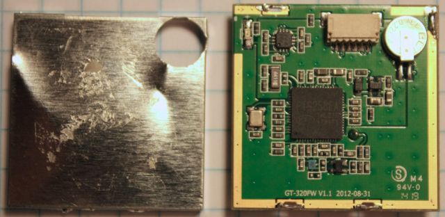
In any case, I removed the GPS module to take a look. It’s mounted to a metal mounting bracket by extremely aggressive double-sided mounting tape. I had to pry it up with a thin knife blade, and it wasn’t easy!
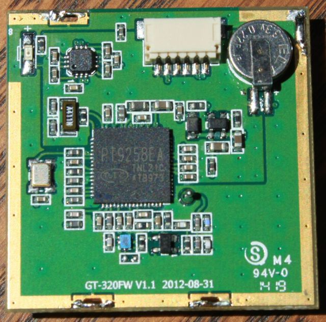
I discovered that my unit actually contains a supercapacitor as the backup power source of this redesigned GPS module.
Small in size and super in capacitance, the 0.22 Farads capacitor is capable of storing charge for months. Time was that capacitors of such magnitude where unheard of. Now they’re readily available for backup power applications.
They say the batteries can be replaced if you are comfortable soldering surface-mount electronic components.
I can’t speak to the battery version of these modules. But in my case, I decided I’d try replacing the supercapacitor. It worked! Case closed – until the problem popped up again some ten months later!
It made no sense that the capacitor would fail a second time. I wondered what was going on?
What I came up with was that somehow, through a firmware bug or some unlikely (and untested) combination of inputs, the GPS chip may enter an indeterminate state. My theory continues, that what’s needed is a complete reset of the GPS. But simply removing the power or disconnecting the module isn’t enough. The supercapacitor continues its job of powering the internal memory of the GPS chip.
When I first replaced the capacitor I had inadvertently reset the GPS by removing the old capacitor. The solution then? Just discharge the capacitor!
Testing my theory should be simple enough. I could discharge the capacitor by shorting its positive terminal to the metal shield of the module (after ensuring the telescope wasn’t powered).
But shorting the 0.22 Farad capacitor probably isn’t a good idea. It’s 0.22 Farads after all, and storing energy is its purpose. I decided it would be better to discharge it through a resistor to limit the current. I used a 1K resistor at first, but that takes too long. I decided instead after the most recent incident in April, 2018, to use a 47 ohm resistor that I had on hand. 47 ohms will limit the peak current flow to about 70 mA, which I imagine is a small enough value not to harm anything.
The time constant of an R-C circuit is simply resistance times capacitance and in this case that’s 0.22 x 47. Both quantities are in basic units which makes the math really easy.
That comes out to 10.34 seconds 63% (one electrical time constant of an R-C circuit is the time necessary to charge/discharge the circuit to 63% of it’s final value). The capacitor was initially charged to about 2.9 volts, so about two time constants should drop the capacitor voltage to about 0.4 volts. 20 seconds ought to do it.
I connected the 47 ohm resistor across the input of my DVM instead of directly to the capacitor. This proved convenient and allowed monitoring the process. I then connected the negative DVM lead to the GPS shield and held the positive DVM lead to the case of the capacitor – its positive terminal. I held the DVM in place for about 1/2 a minute for good measure.
When I reinstalled the GPS module after the first incident, I noticed that the mounting bracket had a hole roughly in the same location of that of the shield, and thought that by aligning these holes I would have the future ability to easily check the capacitor voltage without dealing with that aggressive sticky tape. Well that paid off. I was able to insert the probe of the DVM through both the mounting bracket and the shield hole to contact the capacitor without removing the GPS at all!
Eureka! Upon reassembling and powering up the telescope (on my back porch in clear view of overhead satellites), the GPS was back up and running! The module contains a red LED which flashes and then illuminates solidly when it is synced up and able to report its location and time information. Before the reset it would only flash. After, it lit up solid within only about two minutes, and the hand controller was ready to perform the solar system alignment.
We’ll see how long this fix holds. I used the scope over several weeks and the GPS has worked fine. If it fails again I can probably perform the entire procedure in about 1/2 hour and then I’ll have another “data point” for comparison. The next question is “why”, but I’ll probably never know beyond my intuition that it’s a result of some firmware bug or unexpected combination of input conditions.
Update April, 2, 2018 – It happened again! This is the third time, but my reset procedure worked again. I used a 47 ohm resistor instead of 1K ohms, which meant I only needed to hold the resistor for a few tens of seconds. I had the whole thing opened, reset, and reassembled in about 1/2 hour.
…And again, this time in mid-June 2019. I added a reset button so I don’t have to hold the resistor. I used a tiny tactile switch and a 24.9 ohm resistor.
