Introduction
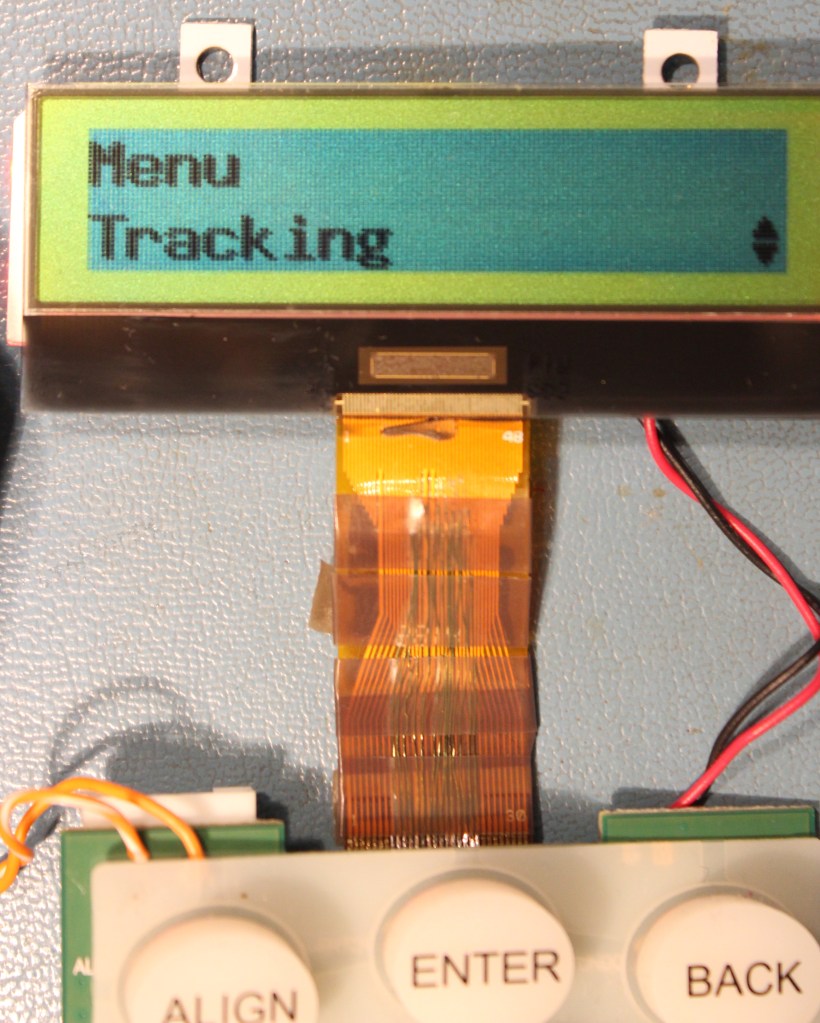
A big lump of metal! That’s what my Celestron CPC-800 telescope amounts to without its NexStar+ hand controller. The GOTO and tracking capabilities are all controlled from the NexStar+ controller – dated though the internal 20-year-old electronics may be.
So, imagine my vexation at the sight of it blinking out one night…fading away…biting the dust…right before my eyes! The LCD became garbled and faded, though the telescope mount continued to respond to the directional controls.
These controllers can be purchased as replacement parts from Celestron. But not surprisingly they are quite over-priced. Celestron is the sole-source for these controllers and corners the market. In any case, these were back-ordered from Celestron and the usual telescope equipment suppliers. Even the auction sites had little to offer. And – I’m just too stubborn to accept that there’s no solution short of entirely replacing the controller.
Thus began my foray into the innards of the NexStar+. There seemed to be no reason why the hand controller decided to die on that particular night. Cycling power brought the LCD back to life temporarily, but that’s far from acceptable considering it means realigning the telescope and perhaps ruining an astrophotography session.
Diagnosing the NexStar+
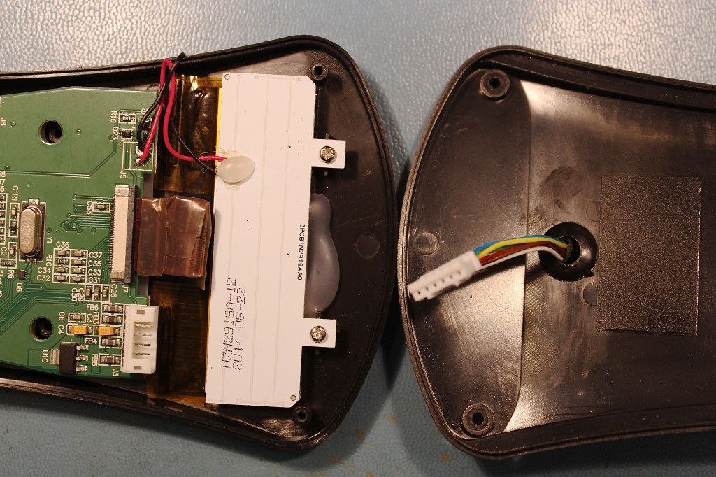
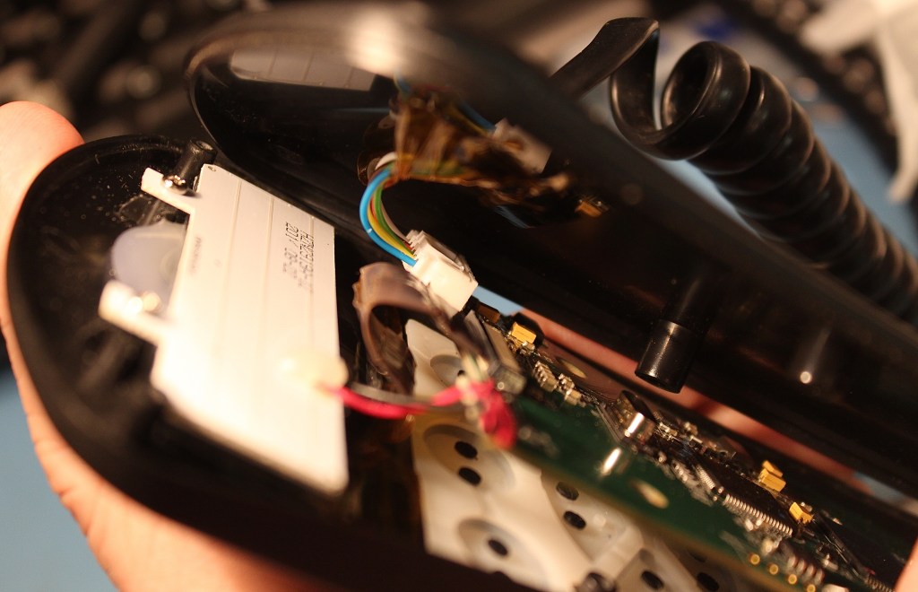
With the hand controller dependent on the telescope for power, it was a bit unwieldy to troubleshoot in its normal configuration. I needed to test the NexStar+ in the more controlled and convenient setting. So, with the controller unplugged and with its coiled cable in hand, I retired to my dungeon workshop to removed six screws and open the housing. I removed the back and unplugged the telescope cable from its internal PCB connector.
Entry of the cable through the housing is problematic. It’s really stuffed in there, leaving not much clearance as it routes past the LCD display and flex-print cable. That, and the cable being quite stiff at its entry point gave me a bit of pause. Could this be part of the problem – the way it’s pressing on the flex-print cable? I was unsure. But I didn’t think the crease was bad enough to break conductors, so I looked other places.
Visual inspection is the first step in any electronics repair. Looking for burned or damage components, loose wires, etc. often reveals clues. No such luck here – everything on the PCB looked good at first glance. The flex-print was still a little suspicious but I knew that would be a pain to deal with. Better to check simpler things like a loose connectors or bad solder joints, and then to probe around a bit.
Next, I traced out the telescope connector to find the power inputs. Pin 2 = Ground, pin 4 = +12v. Soldering a couple of wires to those points on the circuit board allowed easily powering-up the controller from my adjustable, current-limited power supply.
With power supplied thusly, the controller drew about 100 mA or so and would come to life with the LCD scrolling an error message 17. This means it could not communicate with the telescope. No surprise there. But then, I could probe the electronics with relative ease and observe operation of the LCD display on the bench.
I also noticed that the red LED backlights would occasionally fade out after about a second or so, although this was infrequent and seemed unrelated to the LCD problem. But it did raise suspicions of intermittent power and subsequently discharging capacitors. So, the first thing I looked at was the input voltage on the PCB and any voltage regulators.
Yes – always check the power supply, and that includes downstream on-board regulators. It’s a good starting point because these are usually easy to spot and test. I found two regulators and they both checked out fine. These 3.3v and 5.0v regulators were rock-solid throughout my poking around.
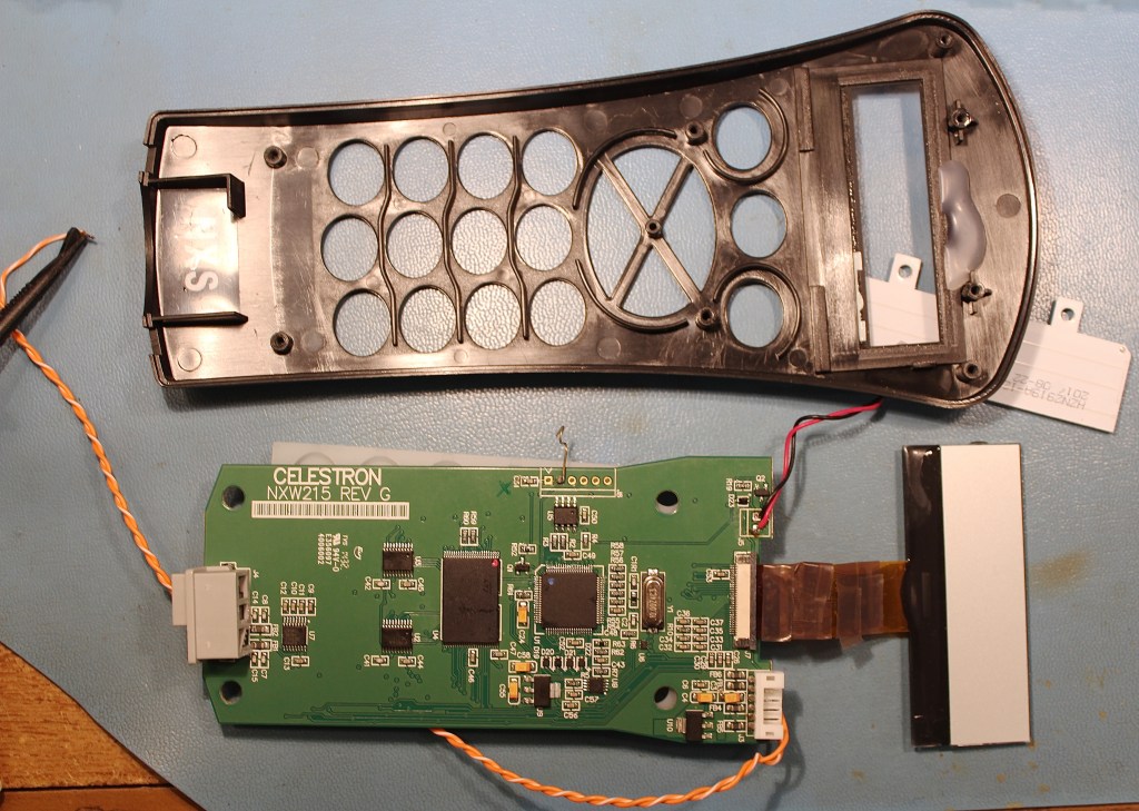
With the rear housing set aside, the PCB was sitting freely in the front half with the LCD and its flex-print being the only thing keeping the PCB in place. I wanted to free those up so I could flip the board around and poke and prod things. The LCD was held on by a few clumps of hot glue, and the backlight by two screws. I removed the backlight and the LCD then easily fell loose from the globs of loose glue. I could then set aside the front housing and finally have the PCB, display and flex-print sitting together on my bench.
The main components on the electronics board are a PIC microprocessor, a memory chip, the two voltage regulators and passive support components. Not that much, really. But anything in there could be the problem. I looked carefully for loose connections and dry solder joints, but could find none. I touched up some of the them up anyway and then replaced one tantalum capacitor that seemed to have some physical damage. Probing the microprocessor’s crystal and a few I/O lines with my oscilloscope revealed these were still active during the fault – so the microprocessor wasn’t dying. I finally turned my attention back to the display.
A little more poking around and moving things would eventually trigger the garbled and fading LCD. Something was loose. But it was extremely touchy and nearly impossible to isolate which mechanical stresses were actually triggering the fault. I couldn’t tell if it was something on the circuit board, the LCD or the flex-print connector. And it was odd that once the fault occurred, that it did not recover even after my poking ceased, as shown in this short video: https://vimeo.com/679786796
The LCD is connected to the board by the aforementioned flexible ribbon cable, a “flex-print”. This is basically a printed circuit board in the form of a thin flexible cable. The conductors are tiny, dense, and thin. One cable end has 30 exposed gold-plated fingers and these mate with a tiny on-board connector. The other end of the flex-print disappears into the glass of the LCD display under a glob of black epoxy. (Although, later I removed black tape from the front of the display, which revealed how the flex-print and COG sit under the epoxy blob.)
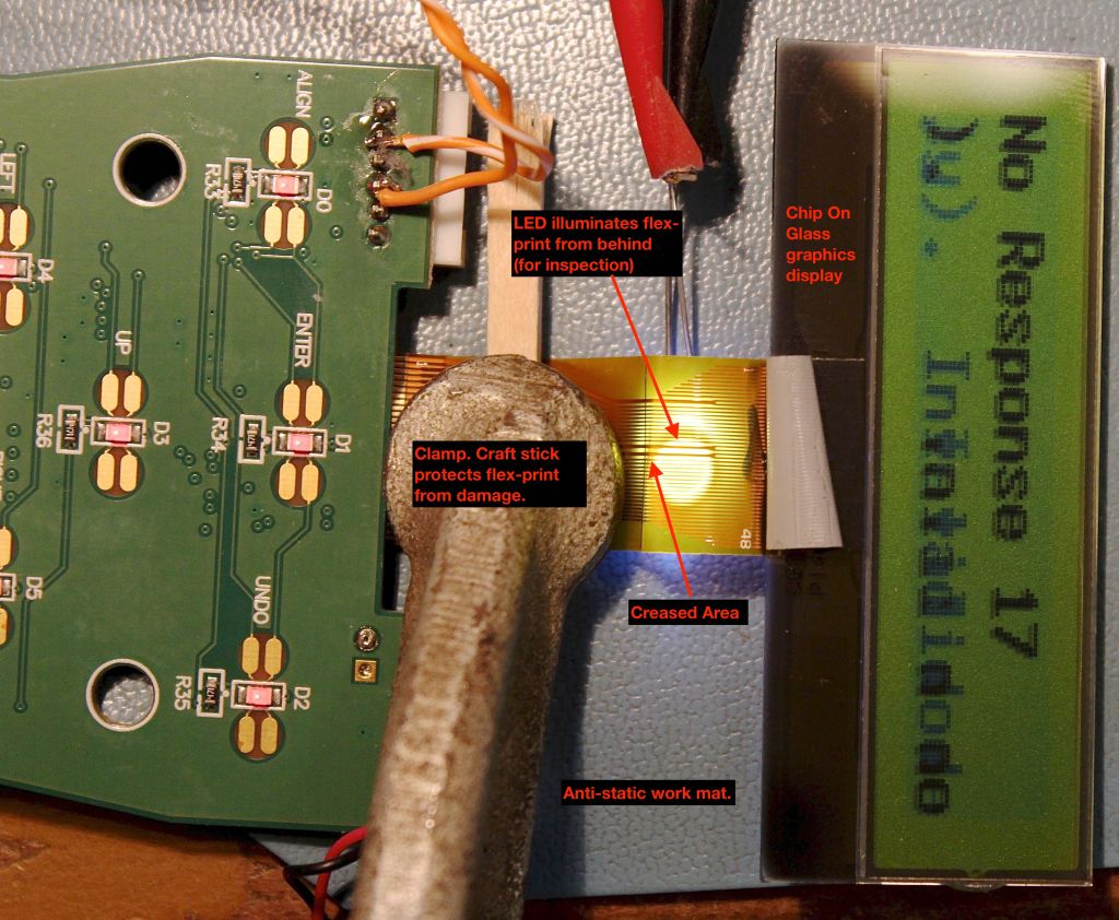
This display is a type referred to as COG, or Chip On Glass – graphic liquid crystal display. It’s a matrix of 144 by 32 dots that are controlled by the COG, which is in turn initialized by the microprocessor at power-up. It’s an interesting thought that there’s a chip involved on the other end of the flex-print! Were that to lose power – even temporarily, it might lose state information and require re-initialization by the microprocessor. That would explain the LCD fault not recovering from the loose connection (until power is cycled), and shift suspicion to the flex-print cable or its connector.
I powered it up again. The display was fine sometimes, but flaked out at others and then at the slightest touch if the cable flexed at certain angles. It was pretty much impossible to tell which end of the flexing printed-cable was inducing the problem. Gently clamping the flex-print flat helped to isolate movements to opposite ends of the flex-print.
The flex-print connector was a prime suspect but reseating it made no difference and wiggling the board-end of the flex-print made no difference either. But wiggling the LCD end certainly did!
I looked more carefully at the suspiciously sharp crease at one point along the flex-prints otherwise sinuous “S” curve. A first look under a microscope revealed no breaks, but I eventually did discover hairline cracks in at least two of the conductors. They could only be seen when the flex print was oriented at just the right angle – and the positioning was ever so sensitive! I guess these finally gave up the ghost due to flexing and pressure where the telescope cable entered from the rear housing – pressing on the flex-print.
Repairing the flex-print
So, I had isolated the problem to the flex-print cable which is integral to the LCD display. Now what? The correct course of action would be to replace the display and cable as a unit. Celestron is not selling this part and I couldn’t find a compatible replacement. And the flex-print is not something that a sane person would try to fix! But who said I was sane?
I could see there were at least two cracked conductors, but the creased area spanned as many as fourteen conductors. So, I carefully scraped the insulation from all fourteen flex-print conductors near the LCD glass and then soldered fine #36 magnet wire across the breaks. It was meticulous and painstaking work that required magnification, a sharp knife, and fine-tipped soldering iron. And steady hands!

Part of my motivation here was simply to verify that the broken flex-print was the only fault. I wasn’t necessarily looking for this to be a permanent repair. But after I reconnected everything – what do you know? It actually worked! No manner of flexing or poking the flex-print would cause the LCD to flake out again. Problem solved and the controller was once again working reliably. Meanwhile, I’ll continue looking for a suitable replacement from among the myriad overseas suppliers of these nondescript COG LCD display modules.
Now as to the fading LED backlights? I never saw that problem again. It solved itself after reseating the LCD connector and/or touching up the microprocessor connections. Or perhaps, the loss of communications with the LCD COG sometimes would cause the microcontroller to respond in this way. The microcontroller does control the backlight intensity in software.
I carefully folded the flex-print back into the housing – taped the telescope cable out of the way to relieve interference, and put it all back together. Time will tell, but the controller has continued to work normally ever since. Take that Celestron!
I’d say it was a worthwhile experience and I learned a few things about these LCD displays along the way. It was quite interesting to examine the display under a microscope, where I could see the COG and flex-print interface in detail. I could see the pixels and some rectilinear spacers that separate the layers of glass. Looking like grains of salt randomly distributed over the surface, I estimate them to be about 7 µm in length – and curiously, their long axes seem to be oriented mostly in the same direction. I could also see the translucent conductors routing to the pixels.

Spacers are about 7 µm in length. Pixels are approximately 375 µm square. Close inspection reveals they are curiously oriented in the same direction.

You continue to amaze and impress!
LikeLike
Thanks! Just too stubborn to give up, and too cheap to buy a new one!
LikeLike
Hi, and thanks for valuable and interesting info!
When you say the hand controller is powered via pin 2 and pin 4, does that correspond to yellow and red cables?
Thanks!
LikeLike
Hey! Sorry for the delay and you’ve probably figured it out by now, but I’m afraid I don’t remember anymore. There may have been some indication of pin 1 on the connector. Otherwise, clues of which was ground and which was power were probably apparent from the circuit traces around the connector and the placement of the tantalum bypass capacitors.
Good luck and have fun!
The hand controller hasn’t given me any trouble since this repair!
LikeLike